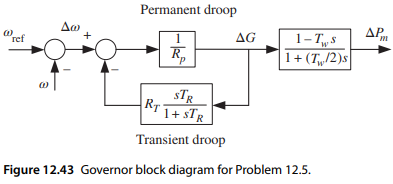
The governor configuration of a hydraulic turbine is shown in Figure 12.43, where Rp = 0.05 and RT = 0.5.
1) Find the transfer function from Δto the gate position ΔG, with the transient droop function included.
2) The system is operating at steady state with = ref = 1.0 pu. Suppose there is a sudden loss of generation in the system such that the system frequency drops quickly, represented by (0+) = 0.995 pu (300 mHz variation at a nominal frequency of 60 Hz). Calculate the incremental gate opening ΔG and the incremental mechanical output power ΔPm at the initial time t = 0+ (instantaneous) and at t = ∞ (steady state). Assume that remains at 0.995 pu in steady state. Repeat the calculation with no transient droop.
Figure 12.43


