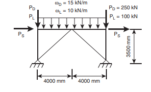
Design the braces, beams, and columns, for the BRBF shown below per AISC 341. Comment on the differences between this design and the SCBF design from Problem 9.1. In that process:
• Assume that the frame is laterally braced in the out-of-plane direction at beam-to-column connections and that the beam is unbraced against compression and lateral-torsional buckling over its entire length. Use simple framing for the beam-to-column connections.
• A seismic lateral load, Ps , of 593 kN is applied at each ends of the frame. That value has already been reduced by the appropriate R value. All loads shown are unfactored.
• Only consider the loading combination of 1.2D + 0.5L + 1.0E and neglect the contribution of vertical ground motion.
• Use a compression strength adjustment factor, β, of 1.2 and a strainhardening adjustment factor, ω, of 1.2.
• Use A992 steel for beam and columns, and A572 Gr. 50 steel for the BRBs.
• Use a rectangular cross-section for the BRBs and W-shapes for the beam and columns.
• When using available design aids, reference the section numbers and edition of the design aids used.


