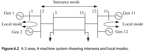
For the two-area, four-machine system shown in Figure 6.2 and used for Problem 6.6, compute the damping and frequency of the three swing modes (two local modes and one interarea mode) using (a) constant-impedance load model for both P and Q loads, (b) constant-current load model for both P and Q loads, and (c) constant-power load model for both P and Q loads. The system data file is provided in the Problem 11.3 folder. Use only the Part 1 operating condition in Problem 6.6.
Figure 6.2

Problem 6.6
(Interarea mode)
1) Obtain the linearized model of the 2-area, 4-machine system in the data file data2aemh.m, using only the electromechanical model data and the constant-impedance load model. Note that in this data set, the inertias of the machines in Area 2 are changed so that the machine and network parameters are not duplications of those in Area 1. In this way a resonance condition in which the local modes of these two areas interact is avoided. Use the PST function svm_mgen to obtain the linearized model and compute the oscillatory modes. Obtain the synchronizing torque coefficient matrix and find its eigenvalues and eigenvectors. Show the mode shapes for the oscillatory modes.
2) Increase the power transfer from Area 1 to Area 2 by changing the load at Bus 4 to 11.76 + j1.0 pu and the load at Bus 14 to 15.67 + j1.0 pu. Calculate the electromechanical modes and compare them with those in Part 1.

