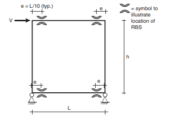
The structure shown in the figure below has RBS connections in each of its two beams. For simplicity in this problem:
• The depth of columns and beams are neglected for this problem (i.e., consider stick-members, as shown in the figure).
• The RBS are located at a distance of L/10 from the columns, and this eccentricity must be taken into account in calculations and in showing the resulting plastic collapse mechanism.
• Mp of the columns is assumed to be sufficiently large to ensure that plastic hinging only takes place in the two beams.
• All beams are W27 × 161. Here: (a) Assuming that the beam flanges have been cut to 50% of their original width, calculate the resulting Mp value at the RBS (in k-ft). (b) Using the upper bound method, find the maximum load, V, that can be applied (in terms of L, h, Mp ), and show the resulting plastic collapse mechanism.


