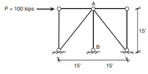
For the braced-frame structure shown here, only answer the following specific targeted questions:
(1) For each of the three cases below, calculate the axial force that will be used to design member A-B, and indicate if it is a tension or compression force.
(a) When that force is obtained using the AISC 341 Amplified Seismic Load approach, assuming that the overstrength factor, Ωo , prescribed in the applicable building code is 2.0 in this case
(b) When that force is obtained by a true capacity design approach consistent with the AISC 341 requirements when the diagonal braces are A500 Grade B HSS 6.000 × 0.312 members
(c) When that force is obtained by a true capacity design approach consistent with the AISC 341 requirements when the diagonal braces are Buckling Restrained Braces (BRBs) (see Chapter 11). For this problem, consider the core of the BRBs’ diagonal braces to be A36 steel plates of area equal to 2 in2 . For this purpose, also use a strain hardening adjustment factor, ω, equal to 1.4, and a compression strength adjustment factor, β, equal to 1.1. Note: Knowledge presented in Chapter 11 is pre-requisite to completing this part (c).
(2) For the SCBF problem in (1.b) above, calculate the member slenderness and compactness of the HSS 6.000 × 0.312. Calculate these values explicitly, rather than using use precalculated or tabulated values of slenderness and compactness. Then, indicate if the HSS 6.000 × 0.312 is admissible to be used as a brace in an SCBF, in accordance with AISC 341. Also note that all members are pin–pin in this frame.


