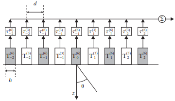
Consider the transducer array shown in Figure P11.6, which has elements that alternate in frequency between 3 MHz (white) and 6 MHz (grey). Assume that each transducer is only able to transmit and receive at its own frequency. Assume L = 90 dB and α = af where a = 1 dB/(cm MHz). In the figure below, let d = h = 0.4 mm. Assume the speed of sound is 1,540 m/s

Figure P11.6 See Problem 11.16.
(a) What is the depth of penetration for the two transducer types? Suppose both arrays will fire simultaneously, sending out sound in the direction θ = 20◦. The 6-MHz system will focus at a depth of z = 5 cm, while the 3-MHz system will focus at a depth of z = 10 cm.
(b) Assuming that T0 fires at t = 0, write an expression for the transmit delays ![]() of the 3-MHz system and compute the actual delay
of the 3-MHz system and compute the actual delay ![]() in μs.
in μs.
(c) Assuming T0 fires at t = 0, write an expression for the transmit delays ![]() of the 6-MHz system and compute the actual delay
of the 6-MHz system and compute the actual delay![]() in μs.
in μs.
(d) Let ![]() and
and ![]() be the amplitudes for the 6-MHz and 3-MHz echoes received from range z, assuming a perfect reflection. The displayed A-mode signals will be switched from the 6-MHz echoes to the 3- MHz echoes when
be the amplitudes for the 6-MHz and 3-MHz echoes received from range z, assuming a perfect reflection. The displayed A-mode signals will be switched from the 6-MHz echoes to the 3- MHz echoes when ![]() reach a signal loss of 30 dB. At what range, zswitch, does this ‘‘switchover’’ occur?
reach a signal loss of 30 dB. At what range, zswitch, does this ‘‘switchover’’ occur?
(e) Find the ratio, ![]() , between the transmit amplitudes of the two systems such that
, between the transmit amplitudes of the two systems such that ![]() at z = zswitch, assuming a perfect reflection.
at z = zswitch, assuming a perfect reflection.

