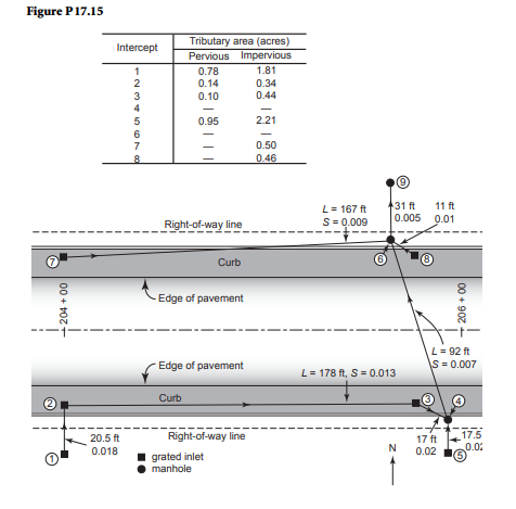
A highway section is as shown in Figure P17.15. The runoff is caught by the grated inlets 1, 2, and 7 at station 204 + 00 and at the gutter sump 8 at station 205 + 78.1. In addition, the runoff from the drainage area to the south of the highway is collected in two inlets, 3 and 5. Inlet 3 connects to inlet 2 and then to manhole 4 at 205 + 95 and inlet 5 directly connects to manhole 4. The runoff from the south side of the highway is then conveyed under the highway to manhole 6, where the north side inlets are also picked up. The accumulated runoff is discharged from manholes 6 to 9 and into a natural water course. The tributary areas and their breakdown between pervious and impervious portions, length of drains, and surface slopes are indicated on the figure. The overland flow time to the intercepts has been considered to be 5 min. The 10-year rainfall intensity (in./hr) is given by i = 149/(t +15.7), where t is in minutes. Design the longitudinal drainage system. C = 0.3 for pervious areas and 0.95 for impervious areas. Use concrete pipe (n = 0.013).
Figure p17.15


