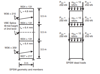
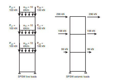
Check the Special Plate Shear Wall shown in the following for compliance with AISC 341. All loads shown are unfactored. Only consider the load combination of 1.2D + 0.5L + 1.0E. (a) Specifically follow the following steps:
(1) Check the adequacy of the web plate thicknesses.
(2) Develop a strip model using a structural analysis program and determine the VBE and HBE axial forces, moments, and shear forces for the gravity and earthquake loads shown below. Adapt the model to recognize that HBEs and VBEs must be designed per a capacity design procedure, assuming that the web plates have developed their expected tensile strength of RyFy. An average tension field angle can be used for the entire wall. The webplates are not allowed to carry gravity load, therefore, tension only members must be used for the web plates, or two models must be developed (one for seismic and one for gravity). (3) Check the VBEs and HBEs for the effects of combined axial force and moment, and for shear force.
(4) Check adequacy of the VBEs moment of inertia.
(5) Check the HBE-to-VBE strong-column/weak-beam requirement. Assume that the HBEs are continuously braced against lateral torsional buckling and braced at their midpoint against compression buckling. Assume that the VBEs are laterally braced in both directions at the HBE-to-VBE connections. The web plates are A36 steel and the HBEs and VBEs are A992 Gr. 50. When using available design aids, refer the sections, page numbers, and edition of the design aids used.


