Calculate concrete dead load camber for Bridge A using:
- Line girder analysis
- Grid analysis
Calculate the dead load camber for steel dead load fit and total dead load fit conditions.
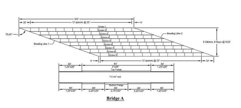
Bridge ‘A’ is an extreme case of straight skew bridges and is used to show extreme skew effects in previous studies. Bridge A has 300 ft. long 144 inches deep girders simply supported on 70.4o skewed supports. The girders of Bridge A are braced with X-type cross frames containing L6 x 6 x 1 angles. The bridge uses staggered cross frames at spacing of 22 ft. between 9 girders at 9.25 ft. c/c spacing. Framing plans and sizes of the web and flanges of the bridges studied are shown in Figure1.
Assume a uniform concrete dead load of 1kip/ft on each girder. Density of concrete is 150 lb/ft^3

Figure1: Framing plans and girder sizes of the Bridge A

